 | |
| Part 4 - Buffering, IDE, Interrupts | |
|
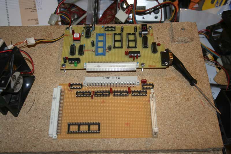
To implement CP/M I needed at least 3 things : more ram, a real UART, the IDE interface. Considering the amount of chips was soon going to be higher than what the Z80 can drive I also needed some form of buffering. UART also meant I needed a baud rate generator and to be efficient I wanted all to be interrupt driven not polling based. The choice for the UART went on the Z80 SIO and about the baud rate generator the CTC been the obivious choice. Buffering been implemented with a combination of 74244 and 74245 with some logic, for the RAM I went for some 32K x 8 static ram chips I also added some space for some extra ROM ( using 8K x 8 EEPROMS actually ) a bit of more I/O decoding ( necessary also for the IDE ) and a couple of extra things. It became soon clear that one non trivial problem was to study a good placement of the components, the chips take up space and also soldering/wiring has some limitations, it really becomes important to find a good placement. It became also clear that a proper "mounting sequence" was necessary cause when you work with "wirewrapping" as I did soon you'll get literally layers and layers of wires and once a layer becomes covered with other wires you can't any more so easily touch/modify what's below. |
1 2 3 4 5 6 7 |
|
|
| Things shaping up | |
|
I began connecting the buffering system cause this has lot of "annoying connections", here I've done a very silly mistake that I discovered a while later. I believed that "everything goes HI-Z during reset", me silly I should have checked the datasheet. Not all does it and you get funny random stuff when you leave a floating bus ... |
|
|
|
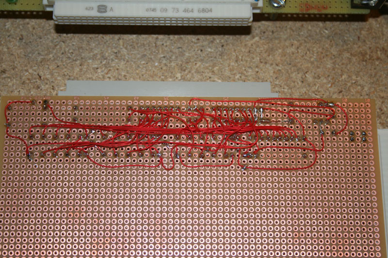
| Buffers wiring | |
|
Here there is not much to say except as I said I've done a minor error leaving some signals floating during reset that should have been not, but the fix been very easy. Next I progressed mounting the IDE interface. After every step like this a full point-by-point check was done to be sure everything was connected where it had to be. |
|
| Prev Back to Main Next | |
| page 4-7 | |